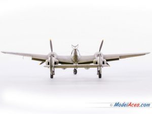
You can greatly enhance the realism of your model aircraft by removing and repositioning parts. Also, going this extra mile can give you the edge in modeling competitions. This is because real aircraft are rarely seen with their control surfaces (i.e. ailerons, elevator, rudder, flaps, trim tabs, etc.) in their neutral or retracted position. Furthermore, because of their demanding maintenance needs, military aircraft are often found in the hanger (or hanger deck) with some hatches and access panels removed. In this article, we will summarize the basic techniques for removing and reattaching plastic model aircraft control surfaces and parts. For an excellent, detailed document with lots of helpful pictures, we recommend downloading this tutorial from the very accomplished modeling instructor Mike Ashey.

First off, don’t be compelled to remove and reattach all of the control surfaces on your model. Think about what will give maxim impact versus effort and risk of damaging the parts. The rudder is typically the first part to consider because its deflection is usually the most noticeable. After that, I usually consider elevators, ailerons and finally flaps respectively. One of the biggest factors that determines the difficulty of removing a control surface is whether or not you need to cut through or around the hinges. On smaller scale models, you can usually cut through the hinge because the hinges are too small to be noticed. As with any model build, take a close look at photos of actual aircraft and drawings to ascertain how much spacing there is between the control surface and the wing. Also look at how much they typically deflect so that your model is a realistic depiction.
The two most useful tools for removing control surfaces are a scribe and a razor saw. Control surfaces on plastic models are almost always separated from the wing by a deeply engraved line or indentation. Start by checking the top and bottom of the wing to see if the control surface engravings are lined up. Don’t assume that they are and plan your cuts accordingly if they are not. After deciding whether or not to cut around the hinges, I usually start by scratching the separation line with a scribing tool while using a straight edge. If there is no engraved channel, use labeling tape to guide your scriber. Keep running the scribing tool in the same direction as you cut deeper.
A razor saw is very useful for cutting from the edge of the wing/control surface in to the first hinge. Again, make sure that you are aware of the top-bottom alignment of the engraved lines. To ensure a clean cut along the intended path, it is a good idea to scribe the path before cutting.
Repositioning trim tabs are another good way to add realism. The good news is that most times they do not need to be removed. You can usually cut the sides free and then bend them up or down. A razor saw is typically the best choice for this. Another nice effect to add realism to trim tabs is to add control cables. Add a control horn to the tab and drill a tiny hole into the corresponding wing. Run a thin stainless steel wire between the two.
After removing and cleaning up the parts to remove excess plastic, there are a number of ways to fill the voids. We typically use plastic sheet stock and/or two-part casting resin. You can cover the control surface or wing edge by cementing on an oversize piece of plastic sheet stock. Once dried, you can trim and sand the edges flush. This is easier than trying to manipulate a tiny piece of sheet stock that you try to cut to size. Another technique to fill the edges is to fill the entire control surface with two-part casting resin. Mask the edges to contain the casting resin and to keep the surfaces neat from and resin spillover. Cut, sand and round the edges according to your documentation and photos.
Check out Mike Ashey’s excellent, highly illustrated book ,“Detailing Scale Model Aircraft” for much more detailed instruction regarding how to manage spacing problems, filling voids, replacing hinges, removing access panels and much more.
That’s a good idea to use a razor saw to help cut through the plastic. I feel like that would be a good way to make sure that you can remove any excess plastic, as well as help all the pieces move. I’ll have to pick one of those up if I decide to get into model aircraft.